


Building a VPN from scratch
by Pranav Joglekar | 2023 August 25th
Section I Introduction
What is a VPN?
A VPN, or virtual private network, is a secure connection between your device and the internet. It accomplishes so by establishing a digital connection between your device and a remote server, owned by a VPN provider, creating a point to point tunnel which enables transmitting all the network data to and fro the internet through this virtual network tunnel. In addition, VPN encrypts your data so that it cannot be read by anyone else, hides your IP address, which makes it more difficult for people to track your online activity and lets you sidestep website blocks and firewalls on the internet. Thus allowing your online experience private, protected and more secure.
The anatomy of VPN:
- Virtual because no physical cables are used in the connection process.
- Private because no one else can see the packets transmitting through this network.
- Network because multiple devices - your device and the remote VPN server connect to establish the secure connection.
Before jumping into technical nuances, let us see where and why VPN is used -
- To protect your privacy: A VPN encrypts your data, so that no one can see what you're doing online. This can be especially important if you're using public Wi-Fi, which is often not secure.
- To access geo-blocked content: Some websites and streaming services are only available in certain countries. If you're traveling or living in a country where a particular website or service is blocked, you can use a VPN to connect to a remote server in a different country and access the content.
- To improve your online security: A VPN can help to protect you from cyberattacks. When you're connected to a VPN, your data is encrypted, which makes it more difficult for hackers to steal your personal information.
- To bypass censorship: In some countries, the government censors the internet. If you're living in a country with internet censorship, you can use a VPN to bypass the censorship and access websites and services that would otherwise be blocked.
How does a VPN Work and Types of VPN
As mentioned earlier,a VPN works by establishing a secure connection between your device and the remote VPN server. Once the connection is established, the two devices behave as they are on a local network and all the network packets from and to the internet are relayed via the remote VPN server.
This connection is like a network tunnel to the outside network/world where your device only sends and receives packets via the tunnel - all the network packets, no matter wherever destined to travel over internet, are passed only via the the tunnel , since, once the connection is established, your device only knows this path to the internet. The other end of the tunnel to which the VPN server device is connected to receives the traffic from your device and relays them to the internet or the outside world - pretending as if this VPN server is sending traffic to the internet. A similar phenomenon happens for the reverse journey of the packets. The packets, not to mention, are encrypted and the IP addresses hidden which add to the security attributes of the VPN - thus making this tunnel connection secure.
This way all traffic traveling out through your device will be sent out by the remote VPN server. The outside world sees all the traffic coming out through the VPN server and feels that this is your device. This way VPNs protect you from online attacks and allow you to access geo-blocked content ( if the remote VPN server is in a place where the geo-restrictions do not exist ). Also, the packets traveling from your device to the VPN server are encrypted. No one, including your ISP or a malicious attacker sniffing your packets will be able to decrypt these packets. This helps you protect your privacy as no one ( except the VPN server ) is able to see what you are doing.
Types of VPN Bridging
Layer 2 VPN
Layer 2 VPN bridging is a networking technology that creates a virtual Ethernet switch between two or more networks. This allows devices on the different networks to communicate with each other as if they were on the same local area network (LAN). Layer 2 VPN bridging operates at the data link layer of the OSI model, which is responsible for transferring data between adjacent nodes on a network. This allows devices to use their native protocols and addresses, and to broadcast and multicast traffic. Layer 2 VPN bridging is useful for applications that require low latency, high performance, or seamless integration, such as voice over IP, video conferencing, or network virtualization.
However, Layer 2 VPN bridging can consume more bandwidth and resources than layer 3 VPN bridging, because it has to carry all the traffic from the source network, including unnecessary or unwanted packets. Layer 2 VPN bridging also exposes more information about the source network, such as MAC addresses, VLAN tags, or ARP requests, which can pose a security risk or cause conflicts. Layer 2 VPN bridging also requires more configuration and management, because it has to handle issues such as loop prevention, spanning tree protocol, or MAC address learning.
Layer 3 VPN
Layer 3 VPN bridging operates at the network layer of the OSI model, which is responsible for routing data between different networks. Layer 3 VPN bridging creates a virtual router that connects devices on different networks as if they were on the same WAN. This allows devices to use different protocols and addresses, and to filter and optimize traffic. Layer 3 VPN bridging is useful for applications that require scalability, security, or flexibility, such as internet access, site-to-site connectivity, or network segmentation.
However, layer 3 VPN bridging also has some drawbacks, such as compatibility, performance, and overhead. Layer 3 VPN bridging can limit the functionality of some applications that rely on layer 2 features, such as broadcast and multicast traffic, VLAN tags, or MAC addresses. Layer 3 VPN bridging can also introduce some latency and degradation in the quality of service, because it has to encapsulate and decapsulate packets, perform encryption and decryption, and apply routing and filtering rules. Layer 3 VPN bridging also adds some overhead to the packets, because it has to include additional headers and trailers for the VPN tunnel.
Introduction to TUN/TAP
As mentioned in the previous sections, a VPN works by creating a tunnel between the client and the VPN server through which all the traffic is transmitted. Also, as mentioned, there are two types of tunnels that can be created - Layer 2 Tunnels used in Layer 2 VPNs and Layer 3 Tunnels used in Layer 3 VPNs.
TUN
Layer 3 Tunnels, which work with IP packets, are called TUN Interfaces ( derived from network TUNnel ). They are virtual devices which simulate a network layer device - they are used for routing traffic ( they cannot be used for bridging ). As we’ll see later these devices are used for creating VPNs.
TAP
Layer 2 Tunnels, which work with Ethernet frames, are called TAP Interfaces. They are virtual devices which simulate a link-layer device - they are used to create a user space network bridge.
Although they have different names and tunnel data through different layers they have many implementation and feature details common and are mostly used together. Unlike regular network devices in a system (physical devices routing packets around via ethernet cables), these devices are completely virtual (software-only) interfaces that have no physical hardware component and simulate those physical connections within the operating system's kernel.
Packets sent by the Operating System through a TUN/TAP Interface can be read by a special user space program which has attached itself to the interface. These programs can also send packets to the TUN/TAP interface, which are then passed to the Operating System and handled accordingly. This results in data being passed back and forth ( a prerequisite for many internet protocols ) as if physical network devices were in use.
A mental model to understand these interfaces is that tun/tap interfaces are regular network interfaces that, when the kernel decides that the moment has come to send data "on the wire", instead sends data to the userspace program that are attached and listening to these interfaces. ( I'll be discussing creating programs to attach to these interfaces soon ). Once a tun/tap interface is in place, it can be used just like any other interface, meaning that IP addresses can be assigned, its traffic can be analyzed, firewall rules can be created, routes pointing to it can be established.
Can TUN & TAP be used together?
Although both are used for tunneling, TUN and TAP can't be used together because they transmit and receive packets at different layers of the network stack. There’s no advantage from using both of them together.
How does my VPN Client work even if I haven’t created a TUN/TAP interface?
VPN clients install TUN/TAP drivers for you when you install the VPN client. As a result, you rarely need to know about these devices – or worry about them. That said, users who have installed various VPN clients may, over time, begin to experience errors caused due to the presence of multiple TAP adapters. Under these circumstances, it is a good idea to uninstall any old VPN clients and TUN/TAP drivers already present in your system. Also, it is worth noting that TUN/TAP devices are only used by certain VPN protocols (such as OpenVPN and WireGuard) and not others (such as IKEv2).
How do programs interfacing with TUN/TAP work?
Whenever a TUN/TAP is created, a special device file is created. When a program interfacing with TUN/TAP attaches itself to the tun/tap interface, it gets a special file descriptor linked to the device file created for the TUN/TAP interface. Reading from this file gives it the data that the interface is sending out. In a similar fashion, the program can write to this special descriptor, and the data (which must be properly formatted, as we'll see) will appear as input to the tun/tap interface. To the kernel, it would look like the tun/tap interface is receiving data "from the wire".
Section II Experiments with TUN/TAP
Tools Required
- OpenVPN
- Tshark
- iproute
Setting up TUN Device
Although you can write a C program to create a TUN/TAP interface, it is out of the scope of this blog. I’ll be using openvpn and ip commands to set up the TUN interface. If you are interested in how an interface is created, you can refer https://backreference.org/2010/03/26/tuntap-interface-tutorial/ .
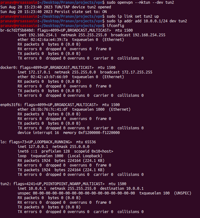
To create a tun device
$ openvpn --mktun --dev tun2
This creates a tun device called tun2. To make this device we need to enabled this device which is done by
$ ip link set tun2 up
Finally, we need to assign an ip address to the device. This is done by
$ ip addr add 10.0.0.1/24 dev tun2
The previous command assigns the ip 10.0.0.1 to the tun device ( tun2 ) and all requests to any address in the 10.0.0.1/24 subnet are transmitted through the tun2 ( and not the default network interface your machine has ).
To ensure that all the set up has been done correctly, you can also run ifconfig and you should now start seeing a new interface which is up with its ip the same as the value we gave it.
Setting up TUN Listener
Just setting up a TUN Device is not enough, to perform something useful you also need a TUN Listener program which reads/writes data from the TUN interface. These listener scripts can do anything you can do with a normal file descriptor. A possible use case could be to read all data that the TUN interface receives and write it to a file, as a log of all data passing through the network. But for the purpose of this blog, our TUN Listener program will be responsible for forwarding the packets to a remote machine – the VPN Server.
The way this works is that both your machine i.e the client and the remote machine i.e the VPN server has a TUN device set up. A similar TUN listener program also runs on both these machines. It creates a socket connection between the client and the server. Whenever a TUN device ( either the client or the server ) receives the packet, the TUN listener program reads this packet and transmits it to the other machine using the established socket connection. At the other machine, whenever the TUN Listener program gets some data from the socket, it transforms it to a packet and writes it to the TUN interface. This way, the network packets are transmitted from one device to another. Although the actual transmission occurs over TCP protocol, for the kernels of the machines, it’s as if the data was received over the wire. That’s why TUN/TAP devices are called virtual devices – they simulate the packet transmission so that the kernel feels that the packets are received over the wire.
A very simple C program which does this can be found at https://backreference.org/wp-content/uploads/2010/03/simpletun.tar.bz2. Please unzip the archive ( it contains a file called simpletun.c ) and compile the program to get an executable. I’ll be using the same executable in this tutorial.
In newer kernels, to be able to use the TUN device, you need to have a TUN Listener program listening on the device. Otherwise, even simple operations like pinging the TUN device would not work as expected.
Note: This simpletun (the file in the archive) directly transfers the packets over the socket connection. But production ready VPNs use protocols like Wireguard, OpenVPN, IKEv2 etc ( https://nordvpn.com/blog/protocols/ ) for first encrypting this data before sending it over the socket. This ensures that the ISPs and malicious sniffers won’t be able to figure out browsing history even if they are able to get access to the packets passing through between the sockets.
Disclaimer: I am not the owners of this code. I'd like to thank the amazing @waldner for creating this elegant piece of software.
Setting up tshark
Seeing is believing. To get the most out of this tutorial, it’ll be better to see the packets as they are being transmitted from and received by the TUN device. tshark is a CLI tool which helps us to do this and we would highly recommend installing and using this tool. It’ll make debugging problems very easy.( https://lindevs.com/install-tshark-on-ubuntu )
Experiments
Finally with all the prerequisites installed and with a rough understanding of TUN/TAP interfaces let’s start with some hands-on experiments.
SETUP
Client Public IP: 10.2.3.1
Server Public IP: 10.2.3.2
Step 1
On the client, we’ll be creating a TUN interface. Run
$ openvpn --mktun --dev tun3 –user <username>
$ ip link set tun3 up
$ ip addr add 192.168.0.1/24 dev tun3
to create the tun interface tun3 on the client and enable it.
Step 2
We’ll also start the TUN Listener program on the client using the command
$ ./simpletun -i tun3 -c 10.2.3.2
where 10.2.3.2 is the server ip.
Step 3
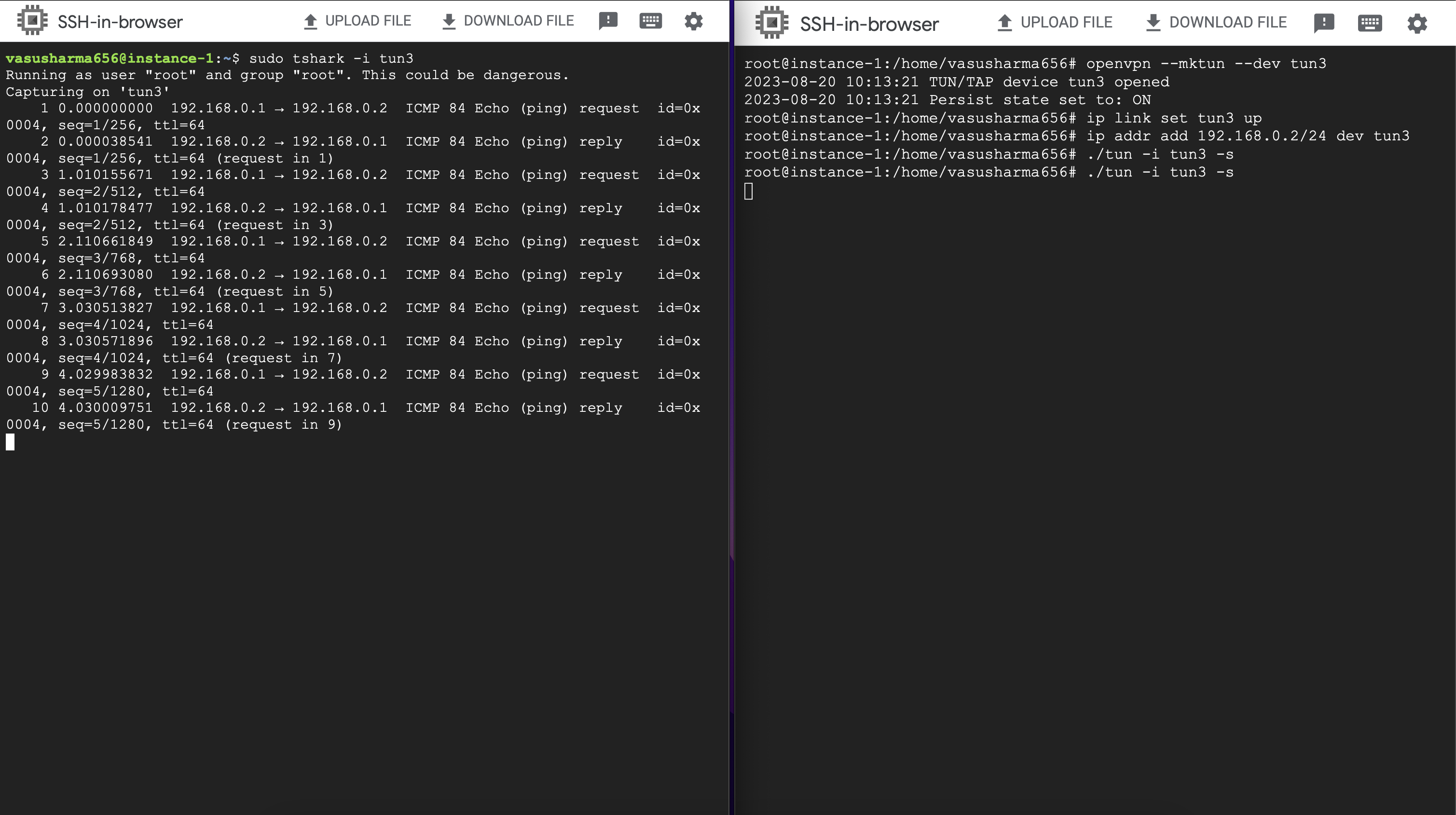
Similarly, we’ll also be setting up a TUN interface on the server. Run
$ openvpn --mktun --dev tun3 –user <username>
$ ip link set tun3 up
$ ip addr add 192.168.0.2/24 dev tun3
to create the tun interface tun3 on the server and enable it.
Step 4 We also need to start the TUN listener program on the server. We do this by
$ ./simpletun -i tun3 -s
with this the client and the server should now be connected by the socket connection and can transfer packets to each other. Congratulations! You’ve set up your first tunnel.
[Client Screenshot][Server Screenshot]
Note: If you encounter some error and want to start again, you can use the following command to delete the created tun interface
$ ip link delete <tun_name>
Experiment 1: Ping to Self
With the setup above completed, let’s start with a simple experiment. From the client, let’s ping the TUN device’s IP address. Without stopping the TUN Listener program, on a separate terminal run
$ ping 192.168.0.1
You should start seeing responses. ( Refer image below )
Let’s check if there’s some traffic passing through our tun interface. On a different window start tshark with
$ tshark -i tun3
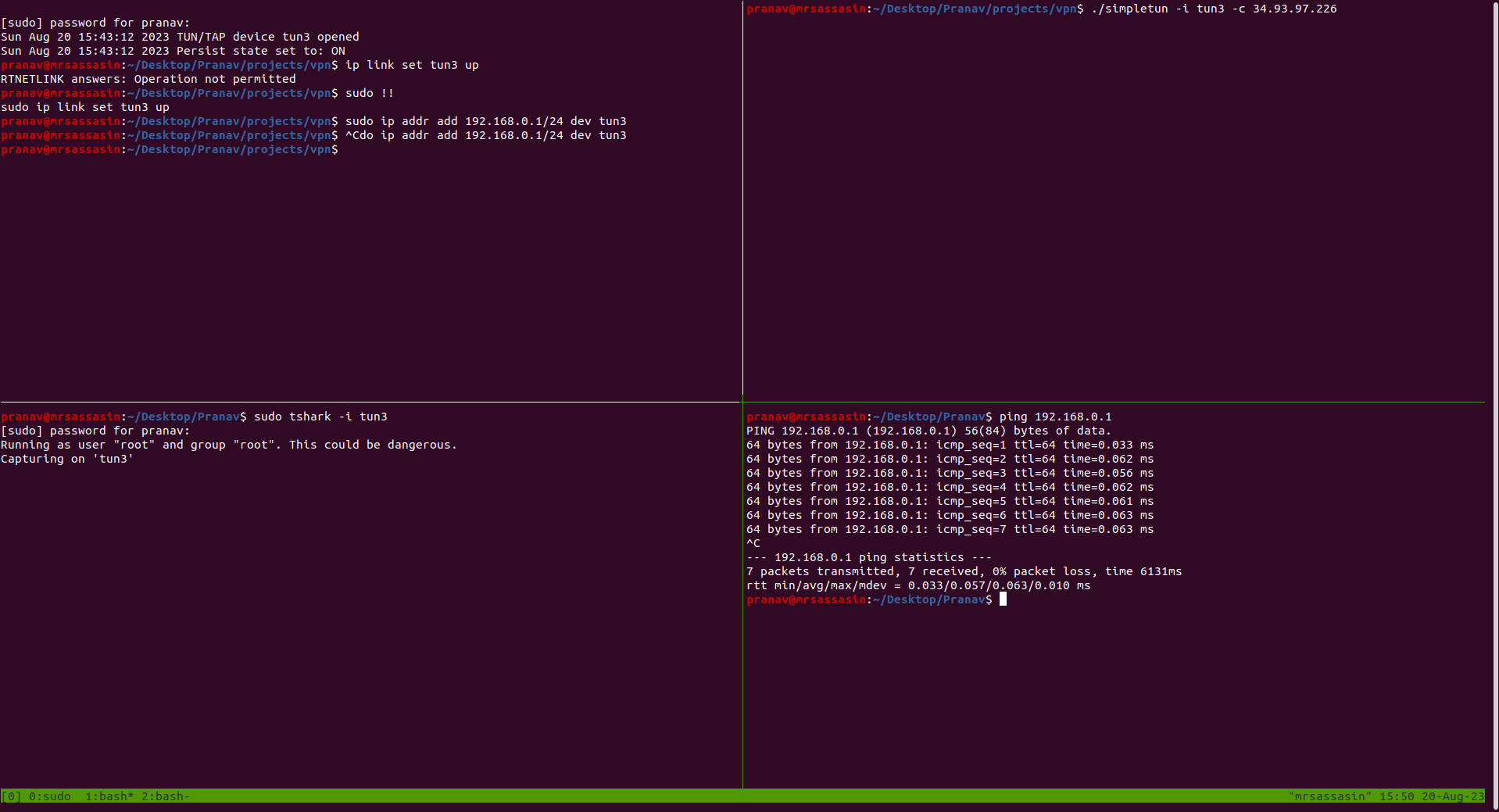
You’ll observe that you don’t see any traffic through tun3. This is expected because since we are pinging the interface’s IP address, the Operating System decides that no packet needs to be sent “over the wire” and the kernel itself replies to the pings. This is the same as the behavior you observe when you ping your default interface’s IP address.
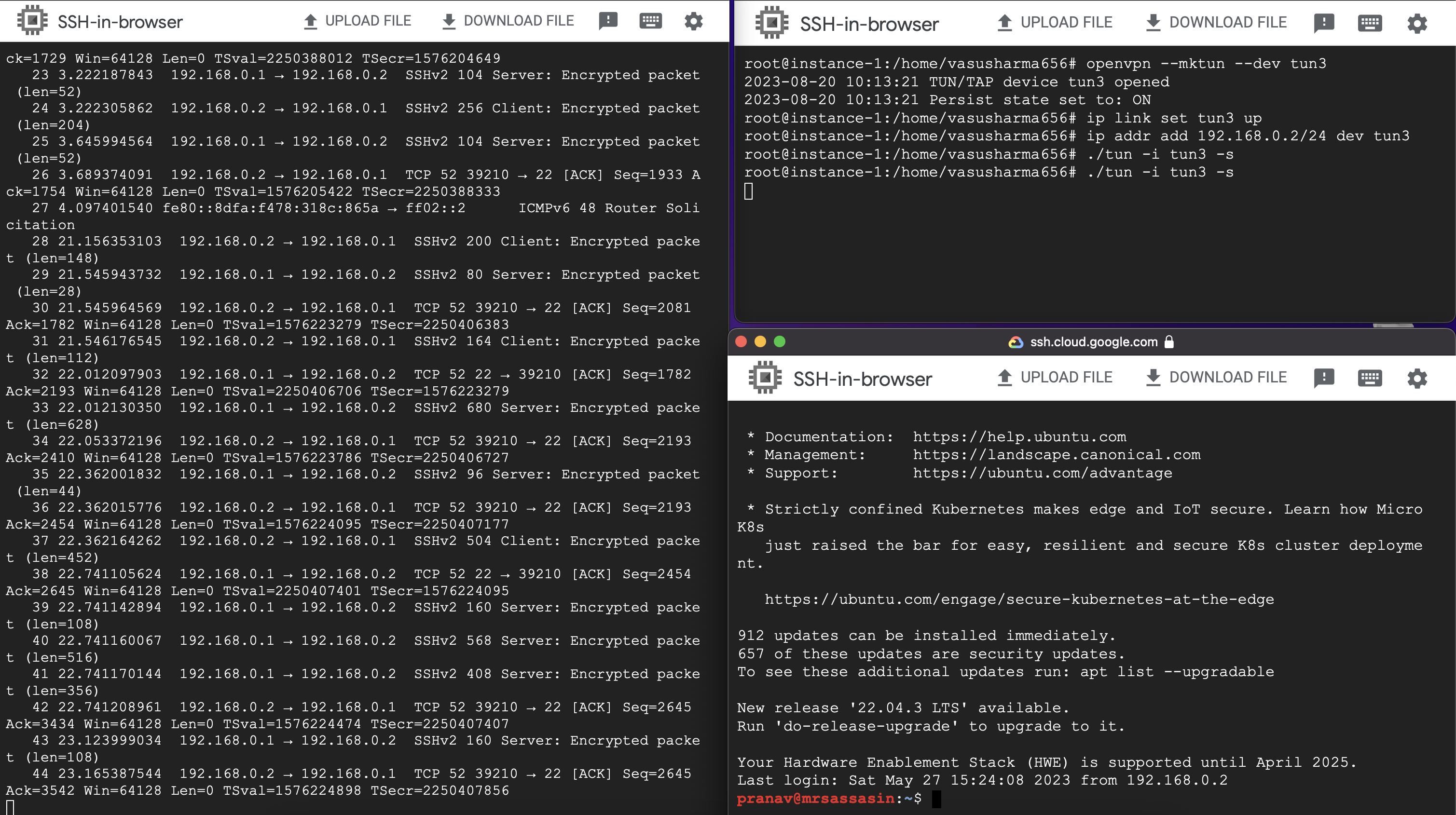
Experiment 2: Ping to Server
Let’s try to ping the server’s IP address now. Run
$ ping 192.168.0.2
and start a tshark listener on a separate window with
$ tshark -i tun3
You should start seeing some traffic on the interface now.
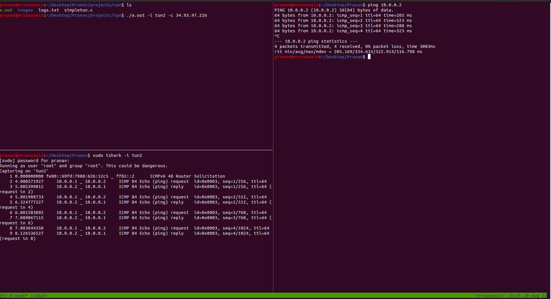
Let’s understand how the packets flow to appreciate what we’ve done.
Whenever you ping 192.168.0.2 the kernel sees that this IP does not belong to a local interface. Furthermore it sees that the route for this exists through the tun3 interface and so it starts sending the packets to the tun3 interface.
Now, whenever the kernel sends these packets to the interface, our TUN Listener program takes over. It sees that the interface has new packets and it starts reading them from the device file and transmitting them to the server through the socket connection. At our server’s TUN Listener program, whenever it gets these packets, it writes them to the TUN interface. After writing them to the server’s TUN, the server’s kernel tries to resolve the ping, sees that a device exists at the ip - 192.168.0.2 and it replies to the pings.
Again, like the client, the kernel ping replies are also handled by tun3 ( server ) and are written to the device file on the server. Like on the client, the TUN Listener program on the server reads these packets from tun3 and sends it to the client using the socket connection. Now, on the client’s end, the TUN Listener will read the packets from the socket and write it to the TUN interface, which will then forward it to the layers above it and finally to the ping program which will then display the output on the terminal.
If you also had a tshark running on the server, you should also be able to see the server receiving and responding to the requests.
Take a minute to appreciate the beauty of what we’ve done. We’ve set up machines thousands of kilometers apart to behave as if they are part of the same network. We’ve set up a virtual network layer connection between two machines without them having a wire.
Q. What would happen if I ping 192.168.0.3 ? ( Assuming there’s nothing at that IP Address )
Similar to the above flow, the ping request would reach the server. The server would send the ping request to 192.168.0.3 but since there’s nothing present at that IP to reply back to the pings it will not get a response back and so it won’t be able to send anything back to the client. The ping would eventually timeout and you would start seeing Destination Host Unreachable errors.
Q. What would happen if there’s no server TUN listener program running or the socket connection is broken
Here, the TUN listener on the client would try to send the packets through the socket but it would fail. This means that the server never received the ping request and so it cannot send a reply back through the socket. The ping would wait for a response, but would eventually timeout with Destination Host Unreachable messages.
Q. What would happen if I enabled the server tun3 on a different IP? Let’s say I ran $ ip addr add 192.168.1.2/24 dev tun3 instead?
In this scenario, once the server receives the request and it sees that it has a device to reply back to the ping, it’ll try to send a response back. But because unfortunately, tun3 on the server is not set up to route traffic to 192.168.0.1 through the tun3 interface, the traffic will be handled through the normal interface. So, tun3 would never receive the packets and so the TUN Listener won’t be able to forward them back. In this case as well the ping program will eventually timeout when it doesn’t get a reply back.
Q. What would happen if we used a TAP interface instead of TUN?
The output would be the same, the only difference is that you’ll also start seeing ARP requests on tshark, because now since TAP is a layer 2 protocol, it’ll first need to get the address to which to forward the requests to. In this scenario, the sockets would transmit all the Layer 2 Ethernet packets between the two remote machines.
Experiment 3: SSH to server to client and vice-versa
Now, Let’s do something even more amazing.
With all this setup in place, the two distant machines start behaving as if they are in the same network. You can also ssh into each other. Let’s try it out. To ssh from the client machine to the server machine run
$ ssh <serveruser>@192.168.0.2
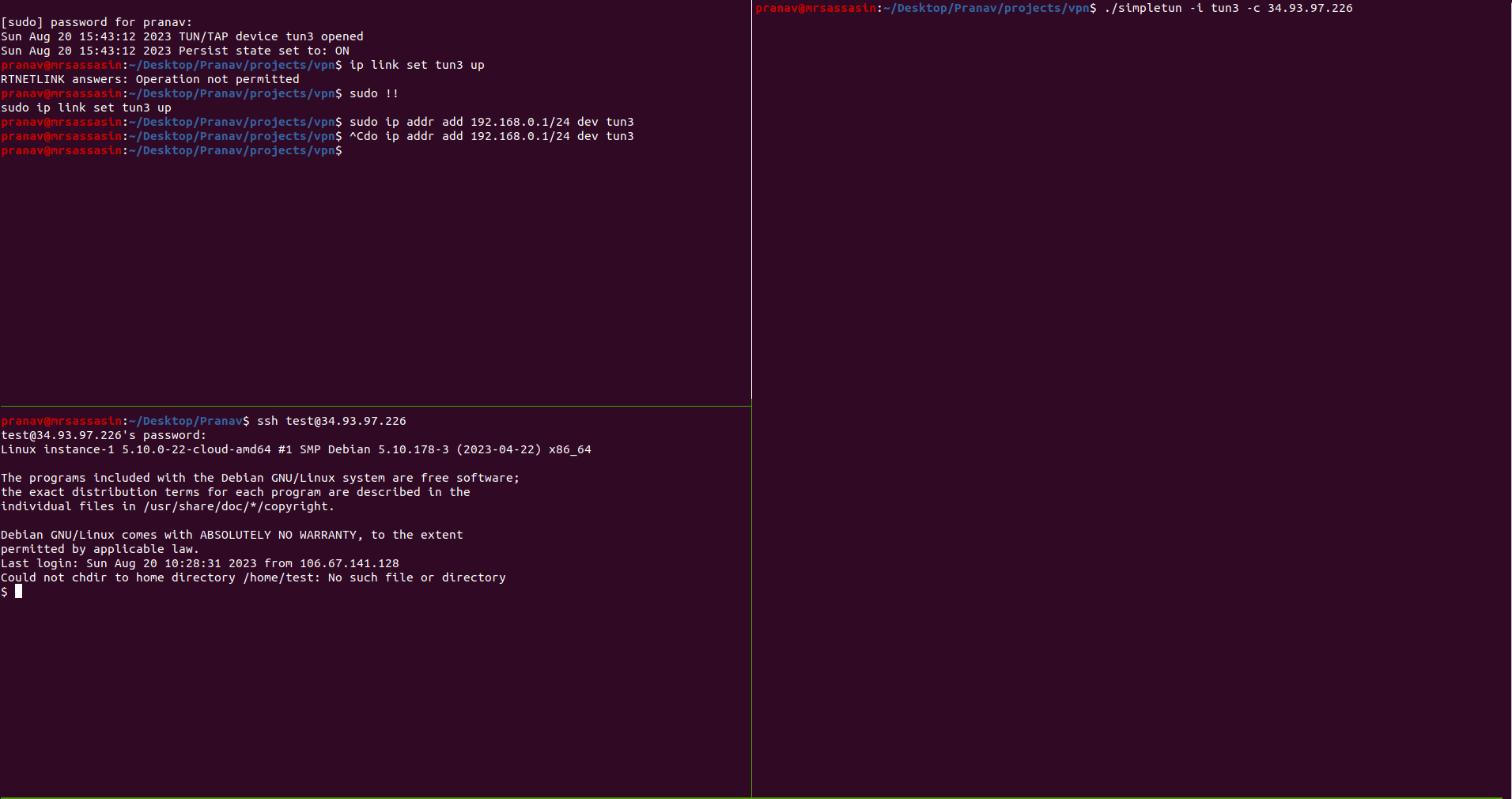
Similarly, you’ll also be able to ssh from the server to the client. Yes, even though the client is behind a NAT. That’s how powerful the setup we’ve built is. Run the following command on the server to try it out
$ ssh <clientuser>@192.168.0.1
This also serves as a good checkpoint to ensure you’re following along. If the above ssh commands work you are ready to proceed further. If not, please try the steps again and read how the packets flow and try to debug your issues.
Experiment 4: Request to a public service
Let’s try to ping google.com ( 8.8.8.8 ) from our client server, but make the request pass through our server. This is essentially what a VPN does. To make this possible we’ll first need to create a new TUN device listening on IP 8.8.8.8 on both the server and the client. Let’s do that first.
Client:
$ openvpn --mktun --dev tun4 –user <username>
$ ip link set tun4 up
$ ip addr add 8.8.8.2/24 dev tun4
$ ./simpletun -i tun4 -c 10.2.3.2
Server:
$ openvpn --mktun --dev tun4 –user <username>
$ ip link set tun4 up
$ ip addr add 8.8.8.1/24 dev tun4
$ ./simpletun -i tun4 -s
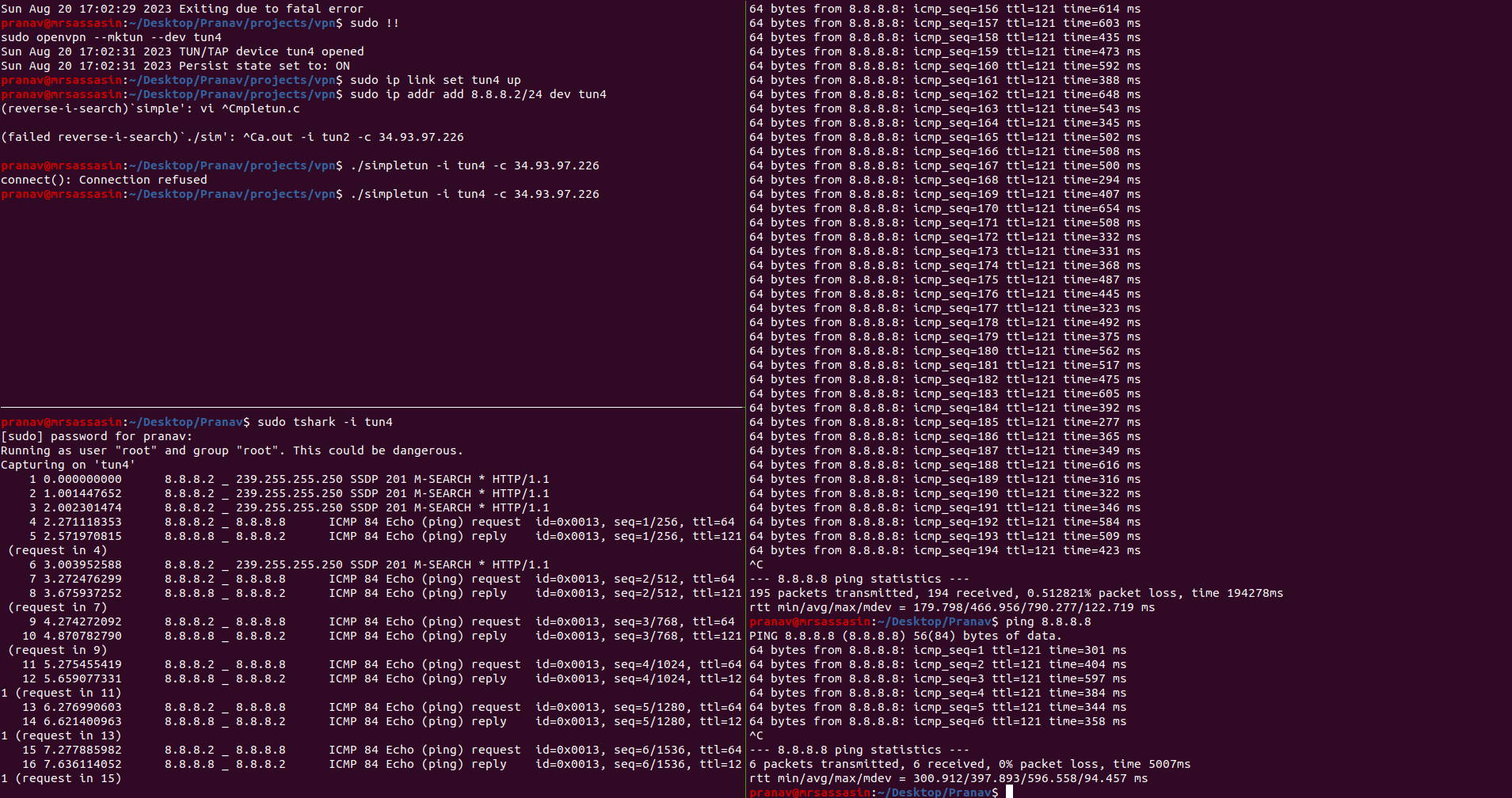
With these setup in place, now if you ping 8.8.8.8 from the client. The packets should be transmitted to the client’s tun4, travel through the socket to the server, be written to server’s tun4 and be forwarded to Google. Unfortunately this doesn’t work.
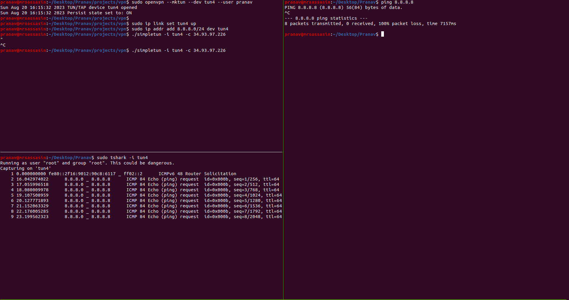
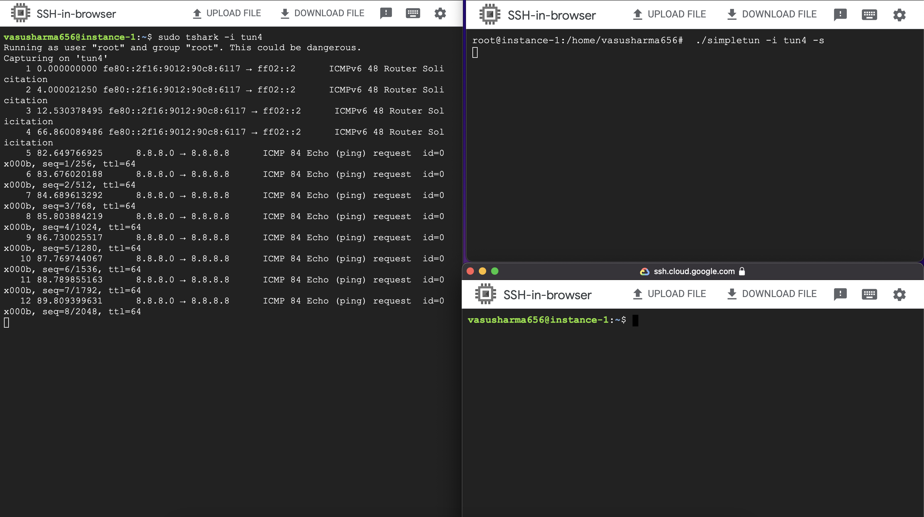
This is because the server’s kernel knows that all requests in the subnet 8.8.8.1/24 are to be handled by tun4 which isn’t connected to the internet so it’ll not send the packets through the default internet connected interface.
You can also verify this on tshark. You should see traffic on the tun4 interface but no traffic through the default internet connected interface.
Plus we’ll also need to modify some kernel firewall rules to allow these kinds of requests and we’ll need to do some minor modifications to the packets that are being transferred. Let’s look at these in the next section.
Section III: Communication with the public world
iptables
On the server, let’s start by modifying the kernel & firewall rules to allow forwarding the packets. This is done by
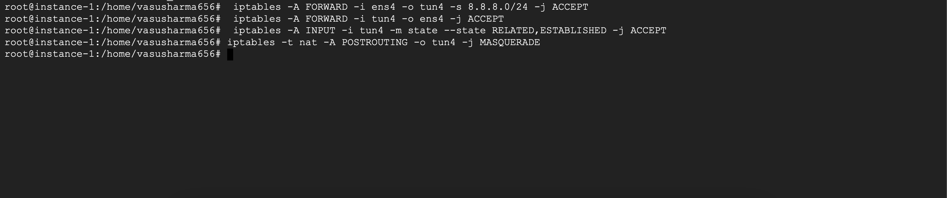
$ iptables -A FORWARD -i eth0 -o tun4 -s 8.8.8.0/24 -j ACCEPT
$ iptables -A FORWARD -i tun4 -o eth0 -j ACCEPT
where eth0 is the default interface connected to the internet. Here,
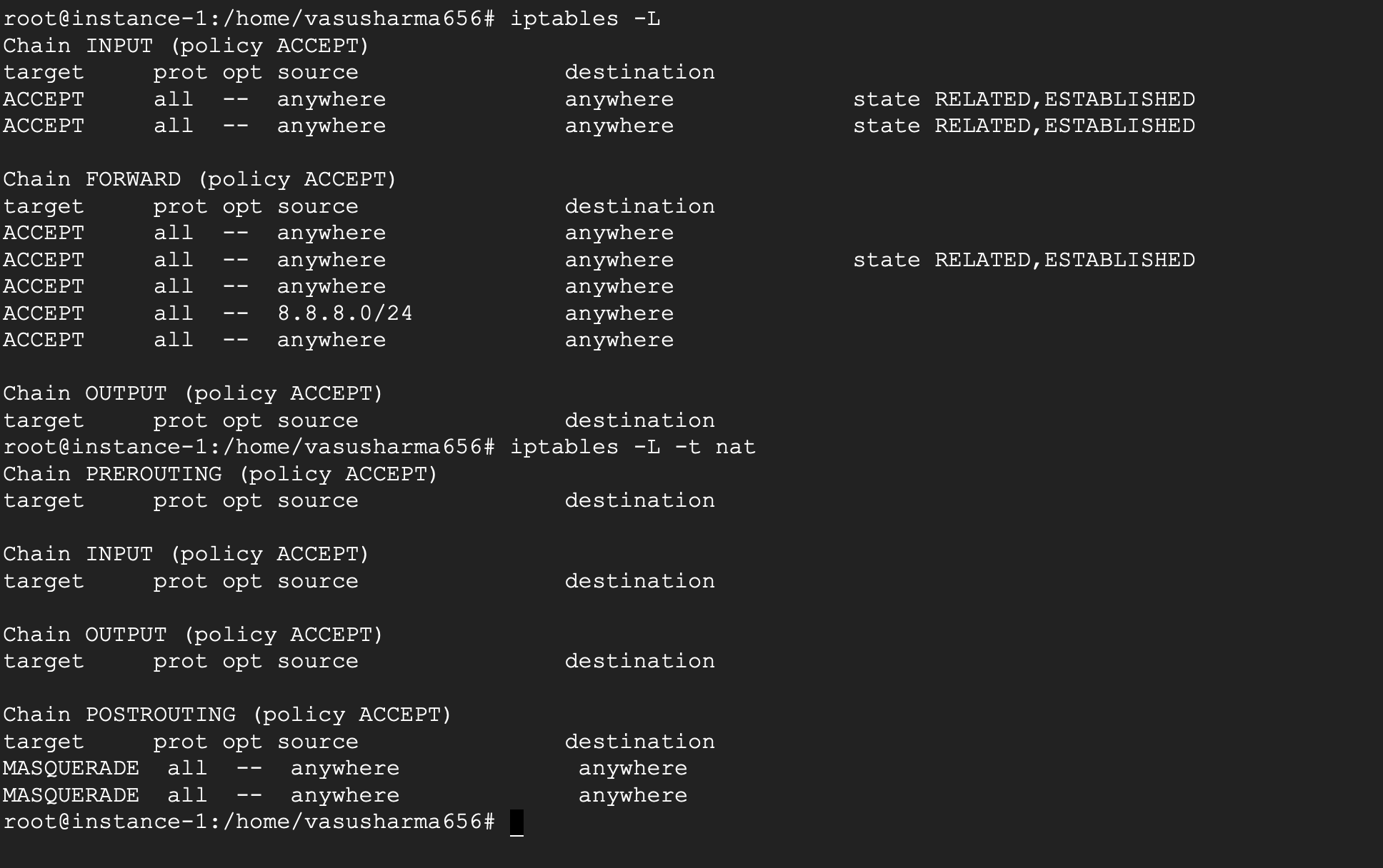
-Adetermines which chain to use. Since we want to allow forwarding packets we useFORWARD.-iand-odetermine the input and output interfaces to use respectively.-sstands for the source for which this rule applies. If no source is passed, the rule applies to all packets.-jdecides what action is to be performed on this rule ( ACCEPT/DENY etc ).
So, the first command allows the kernel to pass packets from eth0 to tun0 interface if the source belongs to the 8.8.8.0/24 subnet.
The second command allows passing all packets from tun0 to eth0. An important concept to understand is that these commands just unblock the firewall rules which allow the forwarding. The actual forwarding will be set up later separately by us.
Another filtering rule that we need to enable is
$ iptables -A INPUT -i tun4 -m state --state RELATED,ESTABLISHED -j ACCEPT
-A INPUTstands for all packets which are destined for the local system.-m state –state RELATED, ESTABLISHEDdecides to filter on thestatevalue ( using the-mflag ) and catches all packets with valueRELATEDorESTABLISHED( using the–stateflag ).
Connections are in ESTABLISHED state once it has received a valid response in the opposite direction. RELATED state connections are connections related to an ESTABLISHED connection. You can learn more about the states here [ https://www.digitalocean.com/community/tutorials/a-deep-dive-into-iptables-and-netfilter-architecture#available-states ].
So this command basically prevents tun4 from creating new connections ( because NEW is not part of the allowed states ) but it allows packets to pass through if a connection has already been established.
Finally to simulate that the packets are being sent out from the VPN server and not the client’s machine, we’ll need to modify the src address of the packets. Unlike the previous commands which just modify the firewall rules, this command actually modifies the packet passing through. We run
$ iptables -t nat -A POSTROUTING -o <default interface> -j MASQUERADE
Here,
-tdenotes that thenattable is to be used, which allows us to manipulate the addresses of the packet.-A POSTROUTINGinforms that the operation is to be performed after the routing has completed-j MASQUERADEis responsible for fetching the IP address of the VPN server and replacing thesrcaddresses in the packet with this IP address.
With the above setup, we’ve updated the firewall and allowed the packets to be modified so that they appear to come from the remote machine. But this is still not enough, we also need to modify the actual routing at the kernel layer to be able to correctly transfer the packets. To do that, we need to understand ip rule and ip route commands.
ip rule & route
To understand these, we need to know that routing happens based on tables, rules & routes. Each table has many route s which determines how the packets are to be forwarded. There can be multiple tables and which table is to be used is determined by rules.
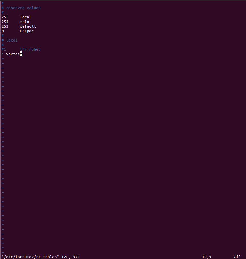
For this example, let’s create a new table vpn. We do this by adding a new entry to the /etc/iproute2/rt_tables. Add an entry at the end of the file prefixed by a number.
Next we add the rule
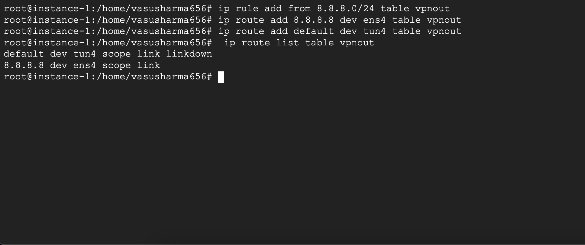
$ ip rule add from 8.8.8.0/24 table vpn
which signifies that any traffic from 8.8.8.8/32 is to be handled by the vpn table.
Finally, we add the following routes to the vpn table -
$ ip route add 8.8.8.8 via <internet gateway ip> dev eth0 table vpn
This adds a routing condition that all traffic to any ip in the subnet 8.8.8.0/24 will be handled by the eth0 interface ( set by the dev eth0 flag. dev stands for device. ).
NOTE:
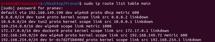
The internet gateway ip can be obtained from ip routes of main routing table using command:
$ ip route list table main
Also, to allow other communication to the tun device to proceed as intended, we also add the route
$ ip route add default dev tun4 table vpn
which routes all traffic (default) through the tun4 interface.
If this command fails with an error, you can verify the current routes with
$ ip route list table vpn
If there exists a route in the vpn table for default. You’ll need to delete the older route using
$ ip route delete default dev eth0 table vpn
With these changes in place, we’ve set and approved a path for the packets to travel to the internet through the VPN server. Try pinging google again from the client. And it should work this time.
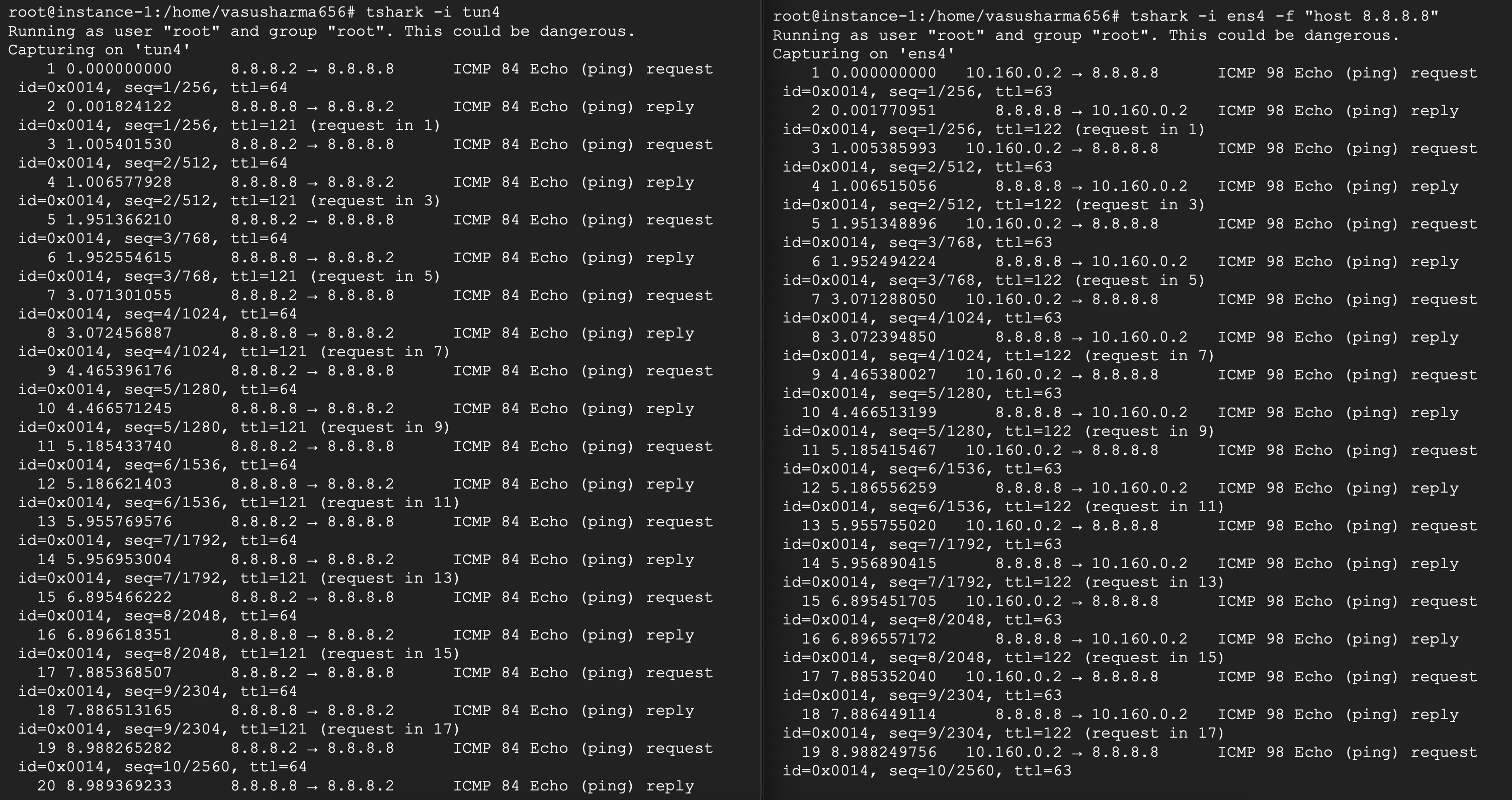
Congratulations! You’ve sent your first request out through your VPN. But these configurations were just for forwarding requests to google. In the next step, we’ll look at allowing all requests to pass through the VPN server.
Section IV: Setting up the VPN
Now that we’ve able to set up a path to ping google which goes through our remote VPN server. Let’s improve our client side setup so that all requests pass through the server, essentially completing the VPN setup.
We do this by configuring all traffic to be handled by the tun interface. But one thing we need to be careful about is that the client-server communication has to happen through the default internet connected interface.
Let’s start by completing the client side setup. As expected, we create a new tun interface and turn it on
$ openvpn --mktun --dev tun5 –user <username>
$ ip link set tun5 up
$ ip addr add 210.212.183.1/24 dev tun5
$ ./simpletun -i tun5 -c 10.2.3.2
Now, as we know all requests in the subnet 210.212.183.0/24 will be handled using tun4. Since we want all requests to be handled by tun4, we update the ip routes using
$ ip rule add from 0.0.0.0/0 table vpn
$ ip route add default dev tun5 proto kernel scope link src 210.212.183.1 table vpn
$ ip route add 10.2.3.2/32 via <internet gateway ip> dev <default interface> table vpn
Using the above commands, we add a new rule such that all traffic uses the vpn table. ( We’ll need to create the table vpn first if it doesn’t exist ). Then we add routes such that all traffic except for the traffic between the vpn server and client happens through the tun interface.
Similarly on the server, we create the new tun interface and set up all the ip routing and forwarding ( with minor changes) as discussed before
$ openvpn --mktun --dev tun5 –user <username>
$ ip link set tun5 up
$ ip addr add 210.212.183.2/24 dev tun5
$ iptables -A INPUT -i tun5 -m state --state RELATED,ESTABLISHED -j ACCEPT
$ iptables -A FORWARD -i eth0 -o tun5 -s 0.0.0.0/0 -j ACCEPT
$ iptables -A FORWARD -i tun5 -o eth0 -j ACCEPT
$ iptables -t nat -A POSTROUTING -o eth0 -j MASQUERADE
$ ip rule add from 210.212.183.0/24 table vpn ( After creating table vpn if it does not exist )
$ ip route add default via <internet gateway ip> dev eth0 table vpn
$ ip route add 210.212.183.2 dev tun5 table vpn
$ sudo sysctl net.ipv4.ip_forward=1
$ ./simpletun -i tun5 -s
This should complete the VPN setup. Any requests the client makes would now be forwarded through the VPN server. You can try this by pinging any ip address and seeing the packets on tshark. Alternatively you can also use sites like https://webhook.site/ and see the IP address of the requestor when you send a request – the ip of the VPN server should be seen. Your client is safely hidden behind the VPN.
Congratulations on building your own VPN! Thank you for following along.